Distributed Lookup Services
Distributed Hash Tables
December 5, 2012
Introduction
Distributed Lookup Services deal with the problem of locating data that is distributed among a collection of machines. In the general case, a lookup service may involve full-content searching or a a directory-services or structured database query approach of finding data records that match multiple attributes.
We limit the problem to the common task of looking up data that is associated with a specific, unique search key rather than, for instance, locating all items whose content contains some property (e.g., locate all files that contain the word polypeptide). The unique key with which data is associated may be a file name, shopping cart ID, session ID, or user name. Using the key, we need to find out on which node (of possibly thousands of nodes) the data is located.
Ideally, the machines involved in managing distributed lookup are all cooperating peers and there is should be no central state that needs to be maintained. At any time, some nodes may be unavailable. The challenge is to find a way to locate a node that stores the data associated with a specific key in a scalable, distributed manner.
There are three basic approaches we can take to locating such data:
Central coordinator. This uses a server that is in charge of locating resources that are distributed among a collection of servers. Napster is a classic example of this. The Google File System (GFS) is another.
Flooding. This relies on sending queries to a large set of machines in order to find the node that has the data we need. Gnutella is an example of this for peer-to-peer file sharing.
Distributed hash tables. This technique is based on hashing the key to locate the node that stores the associated data. There are many examples of this, including Chord, Amazon Dynamo, CAN, and Tapestry. We will focus on CAN, Chord, and Amazon Dynamo.
Central coordinator
A central server keeps a database of key → node mappings. Other nodes in the system store (key, value) sets. A query to the central server identifies the node (or, for redundancy, nodes) that hosts the data for the desired key. A subsequent query to that node will return the associated value.
Napster, the original peer-to-peer file sharing service, is an example of this model. The service was focused on music sharing and was in operation from 1999 through 2001, when it was shut down for legal reasons. The central server holds an index of all the music (e.g., song names) with pointers to machines that host the content.
GFS, the Google File System, also implements a central coordinator model. All metadata, including file names, is managed by the master while data is spread out among chunkservers. A distinction is that the contents of each file are broken into chunks and distributed among multiple chunkservers. In Napster, each server held complete files.
The advantage of this model is that it is simple and easy to manage. As the volume of queries increases, the central server can become a bottleneck. With GFS, this issue was ameliorated by catering to an environment of huge files where the ratio of lookups to data reads was exceptionally low. The central server is also crucial to the operation of the entire system. If the server cannot be contacted, then the entire service is dead. In the case of Napster, the entire service was shut down simply by shutting down the server.
Flooding
For flooding, each node is aware of a set of other nodes that are a subset of the entire set of nodes. This makes up an overlay network. An overlay network is a logical network that is built on top of another network. For our needs, an overlay network refers to a group of nodes where each node has limited information about the overall network topology and uses other nodes (typically neighboring nodes) to route requests.
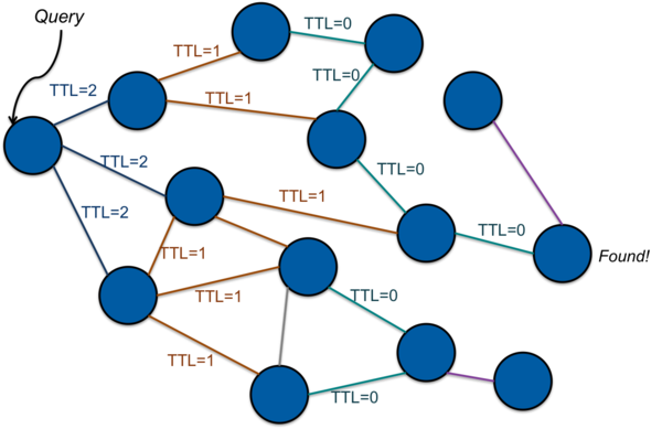
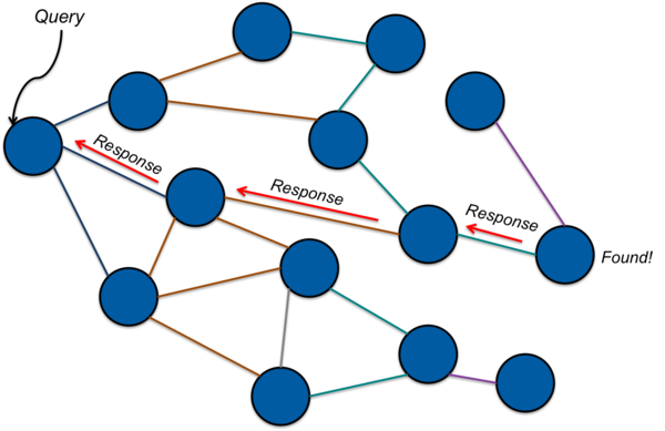
With flooding, a node that needs to find the content corresponding to a certain key will contact peers when looking for content. If a peer node has the needed content, it can respond to the requestor. If not, it will then forward the request to its peers. As long as any peer does not have the requested content, it will forward the request onward to its peers (Figure 1). If a node has the needed content, it will respond to the node from which it received the request in a process called back propagation. This chain of responses is followed back to the originator (Figure 2). For implementations where the data associated with a key is likely to be large (e.g., more than a packet), the response will contain the address of a node. The originator, having now obtained the node’s address, can then connect to the node directly and request the data corresponding to the key.
To keep messages from looping or propagating without limit, a time-to-live (TTL) count is often associated with the message. This TTL count is decremented and the message is discarded if the TTL drops below zero (Figure 1).
This flooding approach is the model that gnutella, a successor to Napster, used for distributed file sharing. Disadvantages to flooding include a potentially large number of messages on the network and a potentially large number of hops to find the desired key.
Hash tables
Before we jump into distributed hash tables, let us refresh our memory of hash tables.
In non-distributed systems, a hash function (the non-cryptographic kind) maps a key (the thing you are searching for) to a number in some range 0 … n–1. The content is then accessed by indexing into a hash table, looking up look up value at table[hash(key)]. The appeal of hash tables is that you can often realize close to O(1) performance in lookups compared to O(log N) for trees or sorted tables or O(N) for a random list. Considerations in implementing a hash table include the following:
Picking a good hash function. We want to ensure that the function will yield a uniform distribution for all values of keys throughout the hash table instead of clustering a larger chunk of values in specific parts of the table.
Handling collisions. There is a chance that two keys will hash to the same value, particularly for smaller tables. To handle this, each entry of a table (
table[i]) represents a bucket, or slot, that contains a collection of (key, value) pairs. Within each bucket, one can use a chaining (a linked list) or another layer of hashing.Growth and shrinkage of the table. If the size of the table changes, existing (key, value) sets will have to be rehashed and, if necessary, moved to new slots. Since a hash function is often a mod N function (where N is the table size), this means that, in many cases, a large percentage of data will need to be relocated.
Distributed Hash Tables
In a distributed implementation, known as a distributed hash table, or DHT, the hash table becomes a logical construct for (key, data) pairs that are distributed among a set of nodes. Each node stores a portion of the key space. The goal of a DHT is to find the node that is responsible for holding data associated with a particular key.
A key difference between DHTs and the centralized or flooding approaches is that a specific (key, value) set is not placed on an arbitrary node but rather on a node that is identified in some way by the hash of the key.
Some challenges with distributed hashing are:
How do we partition the (key, data) sets among the group of nodes? That is, what sort of hashing function do we use and how do we use its results to allow us to locate the node holing the data that we want?
How do we build a decentralized system so there is no coordinator?
How can the system be designed to be scalable? There are two aspects to scalability. One is performance. We’d like to avoid flooding or having an algorithm that requires traversing a large number of nodes in order to get the desired results. The other aspect is the ability to grow or shrink the system as needed. We would like to be able to add additional nodes to the group as the data set gets larger and, perhaps, remove nodes as the data set shrinks. We’d like to do this without rehashing a large portion of the key set.
How can the system be designed to be fault tolerant? This implies replication and we need to know where to find the replicated data and know what assumptions to make on its consistency.
We will now take a look at two approaches to DHTs:
- CAN, a Content-Addressable Network
- Chord
We will then follow up with a look at Amazon’s Dynamo, a production-grade approach to implementing a DHT modeled on Chord.
CAN (Content-Addressable Network)
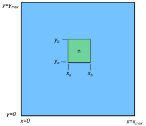
Think of a grid and two separate hash functions hx(key) and hy(key), one for each dimension of the grid. The key is hashed with both of them: i=hx(key) gives you the x coordinate and j=hy(key) produces the y coordinate. Each node in the group is also mapped onto this logical grid and is responsible for managing values within a rectangular sub-grid, called a zone: that is, some range (xa..xb, ya..yb). See Figure 3. The node responsible for the location (i, j) stores (key, V), the key and its value, as long as xa ≤ i < xb and ya ≤ j < yb
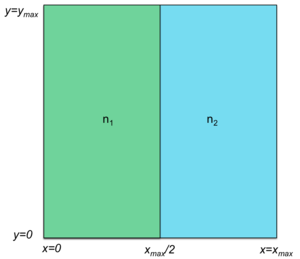
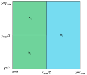
Initially, a system can start with a single node and, hence, a single zone. Any zone can be split in two either horizontally or vertically. For example, Figure 4 shows a grid split into two zones managed by two nodes, n1 and n2. Node n1 is responsible for all key, value sets whose x-hashes are less than xmax/2 and node n2 manages all key, value sets whose x-hashes are between xmax/2 and xmax. Either of these zones can then be split into two zones. For example (Figure 5), zone n1 can be then split into two zones, n0 and n1. These two zones are still responsible for all key, value sets whose x-hash is less than xmax/2 but n0 is responsible for those key, value sets whose y-hash is less than ymax/2.
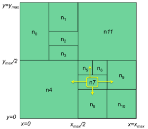
A node only knows about its immediate nodes. For looking up and routing messages to the node that holds the data it needs, it will use neighbors that minimize the distance to the destination. For a two-dimensional grid, a node knows its own minium and maximum x and y values. If the target x coordinate (result of the x-hash) is less than its own maximum x value, the request is passed to the left neighbor; if it’s greater, the result is passed to the right neighbor. Similarly, if the target y coordinate is greater than the node’s maximum y value, the request is passed to the top neighbor; if it’s less then it is passed to the bottom neighbor. If both values are out of range, other nodes will take care of the routing. For example, a request that is passed to the top node may forward the request to the right node if the x coordinate is greater than the node’s maximum x value.
A new node is inserted by the following process:
pick a random pair of values in the grid: (p,q).
contact some node in the system and ask it to look up the node that is responsible for (p,q).
Now negotiate with that node to split its zone in half. The new node will own half of the area.
We discussed a CAN grid in two dimensions, which makes it easy to diagram and visualize but CAN can be deployed for an arbitrary dimension space. For d dimensions, each node has to keep track of 2d neighbors. CAN is highly scalable, although the hop count to find the node hosting an arbitrary key, value pair does increase with an increase in the number of nodes in the system. It has been shown that the average route for a two-dimension CAN grid is O(sqrt(n)) hops where n is the number of nodes in the system.
To handle failure, we need to add a level of indirection: a node needs to know its neighbor’s neighbors. If a node fails, one of the node’s neighbors will take over the failed zone. For this to work, data has to be replicated onto that neighbor during any write operation while the node is still up.
Consistent hashing

Before going on to the next DHT, we will detour to describe consistent hashing. Most hash functions will require practically all keys in the table to be remapped if the table size changes. For a distributed hash table, this would mean that the (key, value) sets would need to be moved from one machine to another. With consistent hashing, only k/n keys will need to be remapped on average, where k is the number of keys and n is the number of slots, or buckets, in the table. What this means in a distributed hash table is that most (key, value) sets remain untouched. Only those from a node that is split into two nodes or two nodes that are combined into one node may need to be relocated (Figure 6).
Chord
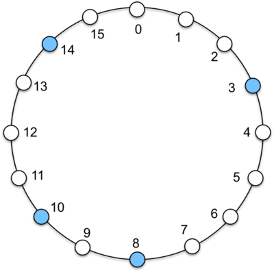
Think of a sequence of numbers arranged in a logical ring, 0, 1, 2 … n, and looping back to 0. Each node in the system occupies a position in this ring that is the number you’d get by hashing its IP address and taking the value modulo the size of the ring hash(IP)mod n. Figure 7 shows a tiny ring of just 16 elements for illustrative purposes. Four nodes are mapped onto this ring at positions 3, 8, 10, and 14. These locations are obtained because the IP address of each node happens to hash to those values. For instance, the IP address of the machine in position 3 hashes to 3. In reality, the hash value for Chord will be a number that is much larger than the number of nodes in the system with a highly unlikely probability that two addresses will hash to the same node.
Each node is a bucket for storing a subset of key, value pairs. Because not every potential bucket position (hash value of the key) contains a node (most will not), data is assigned to a node based on the hash of the key and is stored at a successor node, a node whose value is greater than or equal to the hash of the key. If we look at the example in Figure 7 and consider a key that hashes to 1. Since there is no node in position 1, the key will be managed by the successor node: the first node that we encounter as we traverse the ring clockwise. Node 3 is hence responsble for keys that hash to 15, 0, 1, 2, and 3. Node 8 is responsible for keys that hash to 4, 5, 6, 7, and 8. Node 19 is responsible for keys that hash to 9, and 10. Node 14 is responsible for keys that hash to 11, 12, 13, and 14.
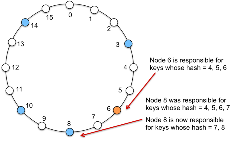
When a new node joins a network at some position j, where j=hash(node’s IP), it will take on some of the keys from the successor node. As such, some existing (key, value) data will have to migrate from the successor’s node to this new node. Figure 8 shows an example of adding a new node at position 6. This node now manages keys that hash to 4, 5, and 6. They were previously managed by node 8. Conversely, if a node is removed from the set then all keys managed by that node need to be reassigned to the node’s successor.
For routing queries, a node only needs to know of its successor node. Queries can be forwarded through successors until a node that holds the value is found. This yields an O(n) lookup.
We can optimize the performance and obtain O(1) lookups by having each node maintain a list of all the nodes in the group and know each node’s hash value. Finding the node that hosts a specific (key, data) set now becomes a matter of searching the table for a node whose value is the same as hash(key) or its successor. If a node is added or removed, all nodes in the system need to get the information so they can update their table.
A compromise approach to having an entire list of nodes stored at
every node is to use finger tables. A finger table allows each
node to store a partial list of nodes but places an upper bound on
the size of the table. The ith entry in the finger table
contains the address of the first node that succeeds the current node
by at least 2i–1 in the circle. What this means is
that finger_table[0] contains that node’s successor,
finger_table[1] contains that the successor after that,
finger_table[2] contains that the fourth (22 successor,
finger_table[3] contains that the eighth (23 successor,
and so on. The desired successor may not be present in the table and
the node will need to forward the request to the lower one on the list, which
will in turn have mode knowledge of closer successors. On average,
O(log N) nodes need to be contacted to find the node that owns a key.
Amazon Dynamo
As an example of a real-world distributed hash table, we will take a look at Amazon Dynamo, which is somewhat modeled on the idea of Chord. Amazon Dynamo is not exposed as a customer-facing web service but is used to power parts of Amazon Web Services (such as S3) as well as internal Amazon services. Its purpose is to be a highly available key-value storage system. Many services within Amazon only need this sort of primary-key access to data rather than a the complex querying capabilities offered by a full-featured database. Examples include best seller lists, shopping carts, user preferences, user session information, sales rank, and parts of the product catalog.
Design goals and assumptions
A full relational database is overkill and limits the scale and availability of the system given that it is still a challenge to scale or load balance relational database management systems (RDBMS) on a large scale. Moreover, a relational database’s ACID guarantees value consistency over availability. Dynamo is designed with a weaker, eventual consistency model in order to provide high availability. Amazon Dynamo is designed to be highly fault tolerant. Like other systems we have looked at, such as GFS and Bigtable, something is always expected to be failing in an infrastructure with millions of components.
Apps themselves should be able to configure Dynamo for their desired latency and throughput needs. One can properly balance performance, cost, availability, and durability guarantees for each application. Latency is hugely important in many of Amazon’s operations. Amazon measured that every 100ms of latency costs the company 1% in sales! [1] Because of this, Dynamo is designed so that at least 99.9% of read/write operations can must be performed within a few hundred milliseconds. A great way to reduce latency is to avoid routing requests through multiple nodes (as we do with flooding, CAN, and Chord’s finger tables). Dynamo’s design can be seen as a zero-hop DHT. This is accomplished by having each node be aware of all the other nodes in the group.
Dynamo is designed to provide incremental scalability. A system should be able to grow by adding a node at a time. The system is decentralized and symmetric: each node has the same programming interface and set of responsibilities. There is no coordinator. However, because some servers may be more powerful than others, the system should support workload partitioning in proportion to the capabilities of servers. For instance, a machine that is faster or has twice as much storage may be configured to be responsible for managing twice as many keys as another machine.
Dynamo provides two basic operations: get(key) and put(key, data). The data is an arbitrary binary object that is identified by a unique key. These objects tend to be small, typically under a megabyte. Dynamo’s interface is simple, highly available key, value store. This is far more basic than Google’s Bigtable, which offers a column store and manages column families and columns within the column families and also allows the programmer to iterate over a sorted sequence of keys. Because Dynamo is designed to be highly available, updates are not rejected even in the presence of network partitions or server failures.
Storage and retrieval
As we saw in the last section, the Dynamo API provides two operations to the application. Get(key) returns the object associated with the given key or a list of objects if there are conflicting versions. It also returns a context that serves as a version. The user will pass this to future put operations to allow the system to keep track of causal relationships.
Put(key, value, context) stores a key, value pair and creates any necessary replicas for redundancy. The context encodes the version and was obtained from any previous related get operation and is otherwise ignored by the application. The key is hashed with an MD5 hash function to create a 128-bit identifier that is used to determine the storage nodes that serve the key.
A key to scalability is being able to break up data into chunks that can be distributed over all nodes in a group of servers. We saw this in Bigtable’s tablets, MapReduce’s partitioning, and GFS’s chunkservers. Dynamo is also designed to be scalable to a huge number of servers. It relies on consistent hashing to identify which nodes hold data for a specific key and constructs a logical ring of nodes similar to Chord.
Every node is assigned a random value in the hash space (i.e., some 128-bit number). This becomes its position in the ring. This node is now responsible for managing all key data for keys that hash to values between its value and its predecessor’s value. Conceptually, one would hash the key and then walk the ring clockwise to find the first node greater than or equal to that hash. Adding or removing nodes affects only the immediate neighbors of that node. The new node will take over values that are managed by its successor.
Virtual nodes
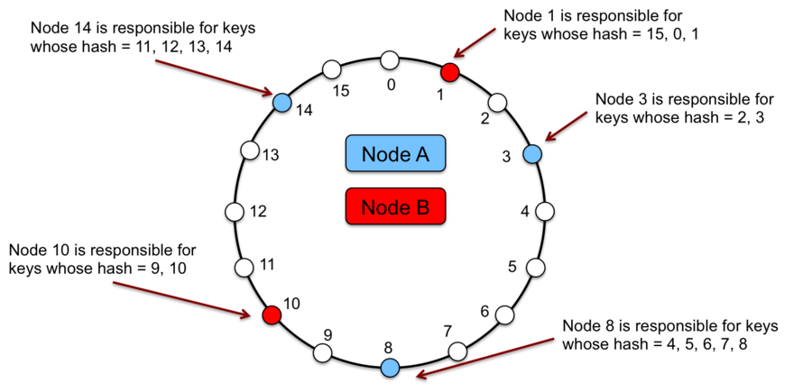
Unlike Chord, a physical node (machine) is assigned to multiple points in the logical ring. Each such point is called a virtual node. Figure 9 shows a simple example of two physical nodes where Node A has virtual nodes 3, 8, and 14 and Node B has virtual nodes 1 and 10. As with Chord, each key is managed by the successor node.
The advantage of virtual nodes is that we can balance the load distribution of the system. If any node becomes unavailable and a neighbor takes over, the load is evenly dispersed among the available nodes. If a new node is added, it will result in the addition of multiple virtual nodes that are scattered throughout the ring and will thus take on load from multiple nodes rather a single server hosting a single neighboring node. Finally, the number of virtual nodes that a system hosts can be based on the capacity of that node. A bigger, faster machine can be assigned more virtual nodes.
Replication
Data is replicated onto N nodes, where N is a configurable number. The primary node is called the coordinator node and is assigned by hashing the key and storing it on the successor node (as described by Chord). This coordinator is in charge of replicating the data and replicates it at each of N–1 clockwise successor nodes in the ring. Hence, if any node is unavailable, the system needs to look for the next available node clockwise in the ring to find a replica of that data.
The parameter for the degree of replication is configurable, as are other values governing the availability of nodes for get and put operations. The minimum number of nodes that must participate in a successful get operation and the minimum number of nodes that must participate in a successful put operation are both configurable. If a node was unreachable for replication in a put operation, the replica is sent to another node in the ring along with metadata - instructions identifying the original desired operation. Periodically, the node will check to see if the originally targeted node is alive. If so, it will transfer the object to that node. If necessary, it may also delete its copy of the object to keep the number of replicas in the system to the required amount. To account for data center failures, each object is replicated across multiple data centers.
Consistency and versioning
We have seen that consistency is at odds with high availability. Because Dynamo’s design values high availability, it uses optimistic replication techniques that result in an eventually consistent model. Changes to replicas are propagated in the background. This can lead to conflicting data (for example, in the case of a temporary network partition and two writes, each applied to a different side of the partition). The traditional approach to resolving such conflicts is during a write operation. A write request is rejected if the node cannot reach a majority of (or, in some cases, all) replicas. Dynamo’s approach is more optimistic and it resolves conflicts during a read operation. The highly available design attempts to provide an always writable data store where read and write operations can continue even during network partitions. The rationale for this is that rejecting customer-originated updates will not make for a good user experience. For instance, a customer should always be able to add or remove items in a shopping cart, even if some servers are unavailable.
Given that conflicts can arise, the question then is how to resolve them. Resolution can be done by either the data store system (Dynamo) or by the application. If we let the data store do it, we have to realize that it has minimal information. It has no knowledge of the meaning of the data, only that some arbitrary data is associated with a particular key. Because of this, if can offer only simple policies, such as last write wins. If, on the other hand, we present the set of conflicts to an application, it is aware of the structure of the data and can implement application-aware conflict resolution. For example, it can merge multiple shopping cart versions to produce a unified shopping cart. Dynamo offers both options. Application-based reconciliation is the preferred choice but the system can fall back on a Dynamo-implemented last write wins if the application does not want to bother with reconciling the data.
The context that is passed to put operations and obtained from get operations is a vector clock. It captures the causal relations between different versions of the same object. The vector clock is a sequence of <node, counter> pairs of values.
Storage nodes
Each node in Dynamo has three core functions.
Request coordination. The coordinator is responsible for executing get/put (read/write) requests on behalf of requesting clients. A state machine contains all the logic for identifying the nodes that are responsible for managing a key, sending requests to that node, waiting for responses, processing retries, and packaging the response for the application. Each instance of the state machine manages a single request.
Membership. Each node is aware of all the other nodes in the group and may detect the failure of other nodes. It is prepared to receive write requests that contain metadata informing the node that another node was dead and needs to get a replica of the data when it is available once again.
Local persistant storage. Finally, each node manages a portion of the global key, value space and hence needs to store keys and their associated values. Dynamo provides multiple storage solutions depending on application needs. The most popular system is the Berkeley Database (BDB) Transactional Data Store. Alternative systems include the Berkeley Database Java Edition, MySQL (useful for large objects), and an in-memory buffer with a persistent backing store (for high performance).
References
Ion Stoica, Robert Morris, David Karger, M. Frans Kaashoek, Hari Balakrishnan, Chord: A Scalable Peer-to-peer Lookup Service for Internet Applications, SIGCOMM’01, August 27–31, 2001, San Diego, California, USA. Copyright 2001 ACM
Sylvia Ratnasamy, Paul Francis, Mark Handley, Richard Karp, Scott Shenker, A Scalable Content-Addressable Network, SIGCOMM ’01 Proceedings of the 2001 conference on Applications, technologies, architectures, and protocols for computer communications, Pages 161–172, Copyright 2001 ACM.
Sylvia Paul Ratnasamy, A Scalable Content-Addressable Network, PhD Thesis, University of California at Berkeley, Fall 2002.
Giuseppe DeCandia, Deniz Hastorun, Madan Jampani, Gunavardhan Kakulapati, Avinash Lakshman, Alex Pilchin, Swaminathan Sivasubramanian, Peter Vosshall and Werner Vogels, Dynamo: Amazon’s Highly Available Key-value Store, SOSP’07, October 14–17, 2007, Stevenson, Washington, USA. Copyright 2007 ACM.
Todd Hoff, Latency Is Everywhere And It Costs You Sales - How To Crush It, High Scalability, July 25, 2009, © Possibility Outpost